In this article
Year 11 Physics Practical Investigation | Acceleration Experiment
Have a physics practical assessment task? Read this complete report on a common Year 11 Physics Practical Investigation and ace your next practical exam.
Looking for Examples of Year 11 Physics Practical Investigations?
One of the most common practical investigations that students perform in Year 11 Physics course is acceleration related experiments. In this article, you’ll find a complete Physics practical report on ‘Acceleration down an inclined plane’ experiment including detailed discussions on experimental errors.
This Year 11 Physics practical report consists of:
Acceleration Down an Inclined Plane
Hypothesis
When an object moves freely down a frictionless inclined plane, its acceleration is directly proportional to the angle of inclination of the plane.
Aim
To determine the relationship between the acceleration of an object down an inclined plane and the angle of inclination of the inclined plane.
Theory
In situations where the acceleration of an object is constant, the following three equations of motion can be used to describe and predict the motion of the object:
\begin{aligned} v&=u+at \\ v^2&=u^2+2as \\ s&=ut+\dfrac{1}{2}at^2 \end{aligned}
where:
- s is the displacement,
- u is the initial velocity,
- v is the final velocity,
- a is the acceleration,
- t is the time interval of the motion in question.
When an object is at rest and remains at rest, its acceleration is zero. When an object is released above the ground and allowed to fall freely, its acceleration is the acceleration due to gravity, g=-9.8ms^{-2}
The negative sign in the value of g = – 9.8ms–2 is used to indicate vertically downward direction.
Hence, when an object is released on an inclined plane and allowed to move freely down the plane, it is expected that the object’s acceleration depends on the steepness of the plane.
Equipment
The following equipment was used:
- Table
- Toy car with smoothly spinning wheels
- Solid inclined plane of 1 metre length with variable inclination
- Box to catch toy car when it travels off the end of the inclined plane
- Smartphone camera or other video recorder.
Safety
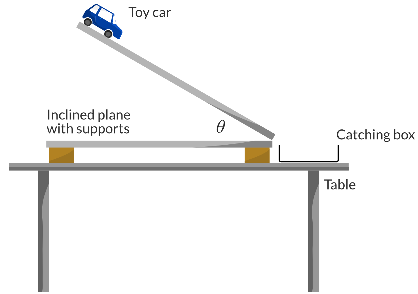
All regular safety procedures are followed (including closed shoes, long hair tied back). Additionally, the toy car is caught by a box (not a person) to avoid possible impact injury. Also the inclined plane is supported by a strong bracket to prevent collapse onto hands while adjusting.
Method
The equipment is set up as shown in the Figure below, where \theta is the angle of inclination of the inclined plane:
The following procedure was used:
- Measure the length of the ramp to confirm it is 1 metre.
- Set the inclined plane to an angle of inclination \theta=10\degree.
- Hold the toy car at the top of the ramp, aligning the back of the car with the edge of the ramp. Have the camera ready to record.
- Start recording video and release the car, without pushing it, allowing it to roll freely down the ramp into the catching box.
- Repeat steps 3-4 twice more.
- Increase \theta by 10\degree.
- Repeat steps 3-6 up to and including \theta=90\degree.
- From all of the video recordings, find the time taken for the back of the car to reach the bottom of the ramp for each trial.
Results
The results for the times taken for the toy car to roll down the ramp are shown in the table below. When \theta=0 the car was not seen to move along the ramp, so no time of travel could be recorded.
| Inclination angle \theta (degrees) | Time (trial 1) (s) | Time (trial 2) (s) | Time (trial 3) (s) |
| 0 | – | – | – |
| 10 | 1.18 | 1.22 | 1.23 |
| 20 | 0.84 | 0.83 | 0.89 |
| 30 | 0.70 | 0.70 | 0.69 |
| 40 | 0.60 | 0.62 | 0.64 |
| 50 | 0.56 | 0.55 | 0.56 |
| 60 | 0.52 | 0.54 | 0.51 |
| 70 | 0.52 | 0.53 | 0.52 |
| 80 | 0.50 | 0.50 | 0.50 |
| 90 | 0.49 | 0.50 | 0.51 |
Quantitative analysis
In quantitative analysis, we are required to:
- Perform calculations and analyse the results of the experiment by plotting and drawing a line of best fit.
- Use the gradient of the line of best fit, in conjunction with control variables, to calculate the unknown variable.
For each value of \theta, find the average time for the toy car to traverse the plane.
| Inclination angle \theta (degrees) | Time (trial 1) (s) | Time (trial 2) (s) | Time (trial 3) (s) | Average Time (s) |
| 0 | – | – | – | – |
| 10 | 1.18 | 1.22 | 1.23 | 1.21 |
| 20 | 0.84 | 0.83 | 0.89 | 0.85 |
| 30 | 0.70 | 0.70 | 0.69 | 0.70 |
| 40 | 0.60 | 0.62 | 0.64 | 0.62 |
| 50 | 0.56 | 0.55 | 0.56 | 0.56 |
| 60 | 0.52 | 0.54 | 0.51 | 0.53 |
| 70 | 0.52 | 0.53 | 0.52 | 0.52 |
| 80 | 0.50 | 0.50 | 0.50 | 0.50 |
| 90 | 0.49 | 0.50 | 0.51 | 0.50 |
From the average time for each inclination angle, find the acceleration of the toy car.
The displacement travelled is s=1\ m, while the initial velocity is u=0ms^{-1}. So acceleration can be found like this:
\begin{aligned} s&=ut+\frac{1}{2}at^2 \\ s&=0+\frac{1}{2}at^2\\2s&=at^2\\a&=\dfrac{2s}{t^2} \\ \therefore a&=\dfrac{2}{t^2} \end{aligned}
The acceleration for each inclination angle is shown in the table below.
| Inclination angle \theta (degrees) | Average Time (s) | Acceleration (m/s2) |
| 0 | – | 0 |
| 10 | 1.21 | 1.37 |
| 20 | 0.85 | 2.76 |
| 30 | 0.70 | 4.12 |
| 40 | 0.62 | 5.22 |
| 50 | 0.56 | 6.48 |
| 60 | 0.53 | 7.22 |
| 70 | 0.52 | 7.29 |
| 80 | 0.50 | 7.94 |
| 90 | 0.50 | 8.02 |
Graph the relationship between the acceleration of the toy car and the angle of inclination of the ramp.
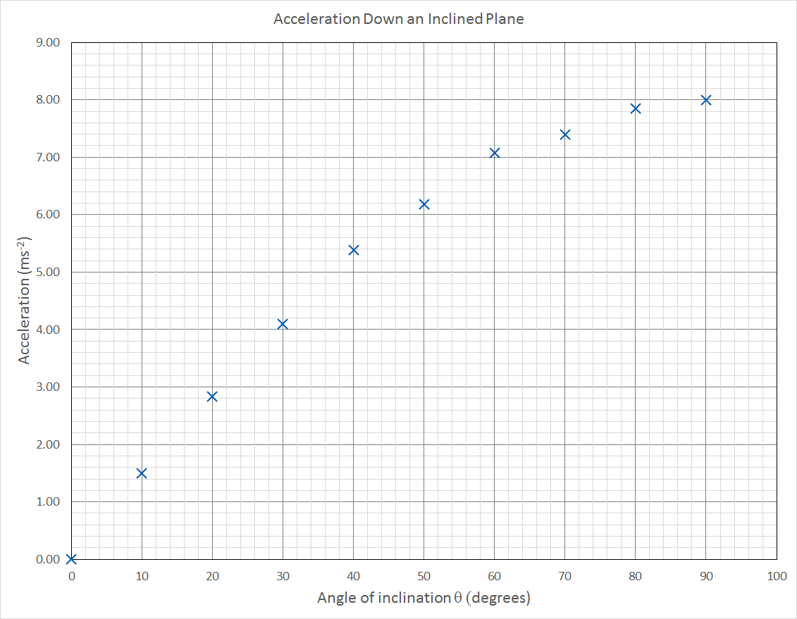
A graph of \vec{a} vs \theta is shown below.
Comment on the relationship between \vec{a} vs \theta . Can a line of best fit be drawn?
The graph shows that acceleration is proportional to inclination angle ( \vec{a} \propto \theta).
The graph also shows that the relationship between \vec{a} and \theta is non-linear, so a line of best fit cannot be drawn.
Non-linear Graphs
Sometimes when we graph data, the relationship appears to be non-linear. This prevents us from drawing a line of best fit and finding its gradient. In such situations it is a useful technique to modify one or both of the axes, in order to make the graph linear.
For example, a parabola with equation y = x2 could be made to look linear by graphing y vs x2 instead of y vs x. That doesn’t mean it is linear (it’s still a parabola!) it just means it looks linear, so a line of best fit can be drawn.
But what axes do we use to make the graph of ā vs θ a linear graph? To do this we would need to understand why the graph is non-linear, which would allow us to predict what sort of function the graph is expected to show.
To understand what function the graph of ā vs θ is expected to describe, we need to discuss gravity fields and specifically weight force, and how the weight force determines acceleration down an inclined plane. This is tackled in Module 2: Dynamics.
For more on drawing graphs for year 11 physics practical investigations, read the Matrix guide on Drawing Graphs and Lines of Best Fit.
Qualitative analysis
In qualitative analysis, we evaluate the method and the experimental errors.
Question 1
Discuss the accuracy of your results. Can the accuracy of all the data points be determined? Does the accuracy of the point at \theta=0 really tell us anything?
The accuracy of all the data points cannot be determined, since the expected relationship between \vec{a} a and \theta is not known. The accuracy of the data point at (\theta=0, \vec{a}=0) only indicates that the inclined plane was indeed completely horizontal for a measured angle of \theta=0.
Only the accuracy of the last data point, where \theta= 90\degree, can be determined since in this case the toy car simply falls straight down. The expected downward acceleration in this case is \vec{a} = 9.8 \ ms^{-2} , but \vec{a} = 8.0 \ ms^{-2} (2 significant figures) was measured. This is a difference of 1.8 \ ms^{-2} which is an 18% difference. This is not very accurate.
Question 2
Discuss possible sources of systematic error that may have affected the accuracy of your results, and suggest improvements.
The toy car is very low mass and does not have a very aerodynamic shape. Hence the air resistance force it encountered would have made it fall slower. Using a heavier and more aerodynamic toy car would decrease the relative amount of air resistance as it fell straight down when \theta=90\degree.
Question 3
Discuss the reliability of your results. Can the reliability of all the data points be determined? Does the reliability of the point at \theta=0really tell us anything?
Since the toy car did not move when \theta=0 and no time to travel could be recorded, the “reliability” of this data point is not useful.Even though the expected relationship between \vec{a} and \theta is not known, the reliability of all data points can be assessed by comparing individual trials with each other, for each value of \theta.
Comparing trials for any given value of \theta shows that the range of values is always within 7% of the average. The steeper angles show even less variability of trials (1-2%) compared to the average.
Question 4
Discuss possible sources of random error that may have affected your results, and suggest improvements.The toy car was released by hand. Even though care was taken to not push the car down the ramp, there is still random error associated with human control of the apparatus.
Using a mechanical gate to hold then quickly release the car would eliminate this source of random error.
For more information on how to perform more advanced data analysis for physics practical investigations read the article on How to Study for Physics Data Analysis Task.
Conclusion
Despite the lack of a relevant theoretical prediction to indicate the expected relationship of \vec{a} vs \theta, we showed that the acceleration of a toy car down an inclined plane is clearly proportional to the angle of inclination. This relationship was clear in the presence of moderately large systematic errors and small random errors.
Access our library of Year 11 Physics Practical Investigations.
Get free access to syllabus specific Physics Practicals written by expert HSC teachers. Join 10000+ students who are getting ahead with Learnable. Try for free now.

Written by DJ Kim
DJ is the founder of Learnable and has a passionate interest in education and technology. He is also the author of Physics resources on Learnable.
Learnable Education and www.learnable.education, 2019. Unauthorised use and/or duplications of this material without express and written permission from this site's author and/or owner is strictly prohibited. Excerpts and links may be used, provided that full and clear credit is given to Learnable Education and www.learnable.education with appropriate and specific direction to the original content.